Every so often I look around for something easy and dramatic to do, rather than face the hard stuff like rusted frame parts. The bus had come with a radiator, although not the one shown in the photos taken at Yeovil, where all the gilled tubes were missing. In all there were enough parts to make three radiators, but I soon found that there were two makers of radiators for TD Leylands: Coventry Radiator and Presswork (CovRad) and Leyland Motors Ltd (LML). Not a single part from one type will fit the other, except the screw cap! So the bits were sorted through to see what would produce the best outcome, which is now a CovRad. Brian Mantle had given me a brand new unused radiator grille, but unfortunately it was for LML, and would be hard to fit neatly. But luckily from somewhere there turned up a CovRad one, a little battered but easily straightened and welded up, and after sandblasting and priming it looked first class. The main difference is that its mounting holes are in different places, and because the vertical grille bars are much closer together in the LML version, there is no way to make new holes without cutting into a bar. Arthur Gillott gave me a brand new filler cap to replace the heavily mauled one. Now all that is needed is the curly bit of pipe that joins to the bottom of the radiator and squeezes past the front chassis crossmember. I have lots of Albion ones, so a bit of judicious cutting and welding may do the trick.
Actually I later found the original Leyland one, carefully placed so I would not lose it, in with the Albion ones in my parts stash.....
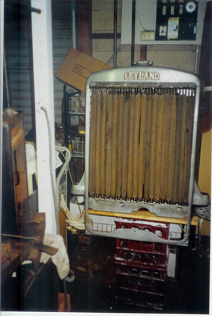
THE COMPLETED RADIATOR MADE FROM THE BITS OF THREE OTHERS AWAITS ITS REFURBISHED GRILLE AFTER BEING WATER-TESTED,
Then, all the top deck window sills (waist rails I discovered recently they are called) were made new and replaced, and the top deck generally rendered structurally intact.
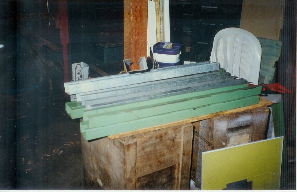
NEW WAIST RAILS (SILLS) MADE FROM ODDS AND ENDS OF SCRAP STEEL LIE READY TO GO IN. THE PHOTO IS DATED APRIL 1998
The flooring of the top deck, which is actually part of the bottom deck, and forms its roof, was rotted for one or two feet in from the front and rear, and for about twelve inches in from each side. It may have been possible to just patch this – but a huge problem arose, of how to curve just three or four feet of new tongue and groove board down at the front and rear. By this time I was getting pretty gung-ho about making and fitting new components, and I decided to simply replace the whole floor, thus giving plenty of leverage to get the front and rear to curve down. Even so, it still proved to be quite an undertaking.
To start with, the top deck had to be lifted clear of the bottom deck. This was no problem. Every single one of the feet of the top deck pillars where they bolt to the floor had rusted away. There was virtually nothing holding the top deck on! One symptom of this fact was that the bottom edges of some of the top deck panels had holes worn in them from rubbing to and fro on the top edges of the bottom deck. A heavy wood and steel beam was made up and inserted under the sills of the second front top deck window, and a heavy screw jack set up over the centre of the very strong bulkhead forming the firewall behind the engine and cab. Gingerly the jack was extended. The beam didn’t bend. The sills (newly fitted) didn’t tear away from the top deck pillars. The firewall didn’t disappear downwards onto the garage floor.
The entire top deck frame lifted 18 inches at the front, AND remained straight from front to rear, without sagging in the middle. The new sills and skirt rail and sections of pillar that had been renewed all took the strain. All credit to the designers of that frame: it is very strong.
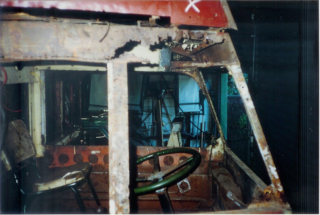
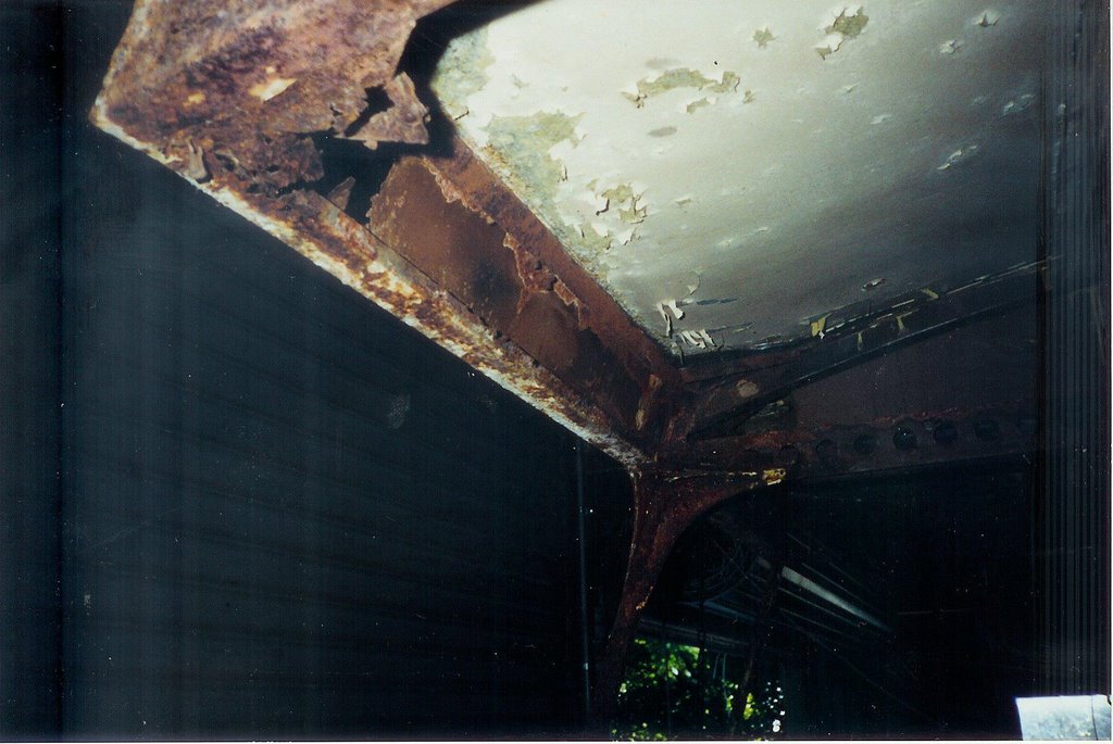
THE OFFSIDE CANT RAIL AND ABOVE IT THE CORNER OF THE TOP DECK; 'X' FOR GOTTA GO
At this point the badly deteriorated lower front corners of the top deck could be accessed easily. They are very complex, having the rounded corner pillar, two skirt rails, and two angle braces all meeting at the one place. Luckily there was a short length of the rounded corner pillar section lying around at Tempe, somewhat different in dimension but having the correct radius curve. The necessary short pieces of skirt rail at side and front, plus the angle braces, could all be made up and welded into place along with new mounting brackets which enable the corners to bolt to the floor at front and side. These corners took weeks, with great care needed to maintain alignment in all directions.

NEW PILLAR BASES HAVE GONE IN ON THE NEARSIDE, AS WELL AS A NEW SKIRT RAIL. THE WIRE AND TURNBUCKLES FROM SIDE TO SIDE OF THE FRAME ARE THERE TO ALLOW IT TO BE ADJUSTED PRECISELY FOR WIDTH, AS WITHOUT ITS FLOOR BRACKETS BOLTED DOWN, THERE IS NOTHING TO PREVENT IT SPREADING AT THE LOWER EDGES
Then came the feet of all the top deck pillars. Compared to post-war deckers, these have huge angled mountings which protrude into the top deck floor area (look upstairs in Leyland 1438 and AEC 1286 to see what I mean). One and one only bracket escaped replacement: the third one from the front on the offside. I kept it for old times’ sake and because it was only slightly corroded. New ones were folded up from metal obtained from Wilkins Servis washing machine panels. These were a boon – 1mm thick, and galvanised and painted.
A VIEW INTO THE TOP DECK FROM THE STAIRWELL, WITH ROTTED FLOOR BOARDS REMOVED ON THE OFFSIDE AND NEW PILLAR FEET IN PLACE. THE SOLE SURVIVING FOOT IS THIRD FROM THE FRONT, STILL IN DARK PAINT.
The vehicle is now an amalgam of Wilkins Servis and Malleys washer, Hoover washer and dryer, Vono bed base and sheets of galvanised iron scrounged from roadside cleanup days and North Ryde waste treatment station! The original oregon floorboards, each of which was one length from front to rear, would be taken up one at a time and replaced with new boards milled to size from recycled hoop pine which I was advised would bend easily without cracking when the time came. However the recycler in West Botany Street Rockdale just smiled when I asked for single boards, some up to eight metres in length. The best they could provide was 5.2 metres. So every board would have to have a join in it somewhere along its length, and care was taken to stagger the joins so they didn’t all occur at one roof bow.
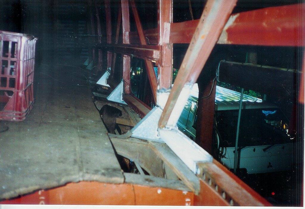
Firstly however, it dawned on me that some of the outer extremities of the lower deck roof bows had rust in them, and so could not have boards screwed to them just yet, and the cant rails (I call them) over the engine and cab were useless.
A VIEW OF THE CANT RAILS OVER THE ENGINE BAY. WITH THE TOP DECK FLOOR REMOVED ACCESS TO THESE WAS A LOT EASIER
A sheet metal firm at Brookvale folded up a new front header rail for over the engine bay and cab. It is seven feet long and the folder at Tempe can only take four feet max. The cant rails, which are curved, were made at Tempe then cut at three or four inch intervals on their inner edges with a hacksaw, and welded up to create a curved box section. With the first three feet of boards torn up at the front, a new ceiling of thin galvanised sheet was laid in over the cab/engine bay.
The diagonal windows on each side at the rear of the bottom deck got new diagonal braces and letter boards above them. The frame over the rear platform entrance was totally remade, using Vono bed base side rails (1.5”x 1.5” angle) and steel strip. The framing under the nearside rear destination box was remanufactured, having been affected by water leaking onto it from the leaky putty around the fixed window above it. The driver’s cab door aperture needed repairs, so that the door could be trial fitted to ensure that the new cant rail above it was in the right place, and the shape of the door space had not suffered from all the goings-on around it.
Brian Mantle was in the background all this time, advising how to curve a box section, how to create a pillar in top hat section, how to ensure a straight line from front to back – in short pretty well everything I didn’t know about sheet metal work. Meanwhile my control over the welder got better and better, until I now feel almost confident about undertaking a weld in any position. However it remains true that welders have minds of their own and have good days and bad. The government should do something about it.
At last the bottom deck around its top edges was good enough to receive floor boards.

FLOOR BOARDS GO IN. THE BEAM AND JACK FOR RAISING THE TOP DECK FRAME CAN BE SEEN. THE WEDGES AND BLOCKS WERE TO AID IN CRAMPING THE BOARDS CLOSELY TOGETHER.
During the process, great care had to be taken to find the sockets attached under two of the boards for seat attachment, which were faithfully reproduced. At this point it was noticeable what a tiny amount of room there is between the upstairs front seats and the front windows. People were nimbler then. After many months of frame repairs and laying of floor boards, the top deck floor was complete. It looked superb in fresh clean hoop pine and it was a shame to think it would all be covered in dirty old bitumen paint and malthoid.
However at the front and rear, uncut edges of floorboard stuck out into thin air. They had to be curved down, mainly at the centre, to meet the header rail at the front and the frame over the back platform at the rear. I thought about this for a long time, having abandoned the idea of steaming the boards to curve them, because each board would have to be steamed and curved before I laid it, making a real nightmare of trying to match the curves perfectly. I had even bought an old copy of Woodwork in Theory and Practice by John A Walton, my old woodwork teacher at Canberra High School, to find out how to make a steamer and do the curving. Relying on the fact that the cant rails and header at the front were new and strong, I thought I would put a beam under these and a strong plank over the floor boards above and try to draw the ends of the plank and beam together with 5/8” threaded rods and nuts at each side.
With all this set up, I started tightening the nuts on the threaded rods. The hefty 12” x 2” builder’s plank just curved up in the middle, and the boards moved down about two or three inches of the six inches needed. Some major weight was needed on the centre of the builder’s plank. The top deck was available, so it was lowered on its jack onto the rear of another beam resting fore and aft on the plank and poking out over the front of the bus, where it was tied with fencing wire to the front chassis crossmember to stop it swinging up. This did the trick, and eventually with the help of lots of kettles of boiling water, the boards agreed to curve down evenly to meet the front header, where they were attached with heavy 1/4” roofing screws, two per board, into the header rail. After a few days I apprehensively took the weight off the jack, but all the planks stayed put. The strength in those planks is one of the major reasons that the four passengers in the front seats don’t fall down onto the engine and driver.
LOOKING FORWARD FROM THE STAIRWELL, THE NEW MALTHOID FLOORING COVERS UP THE BEAUTIFUL HOOP PINE BOARDS
In order to surface the floor the top deck had to be raised again, at its original jacking point, and malthoid was laid, moving the jacking point around a bit to enable the flooring to be laid all the way across. Malthoid is miraculously still available from Hardware and General at Brookvale, but called damp coursing, in up to one metre width.

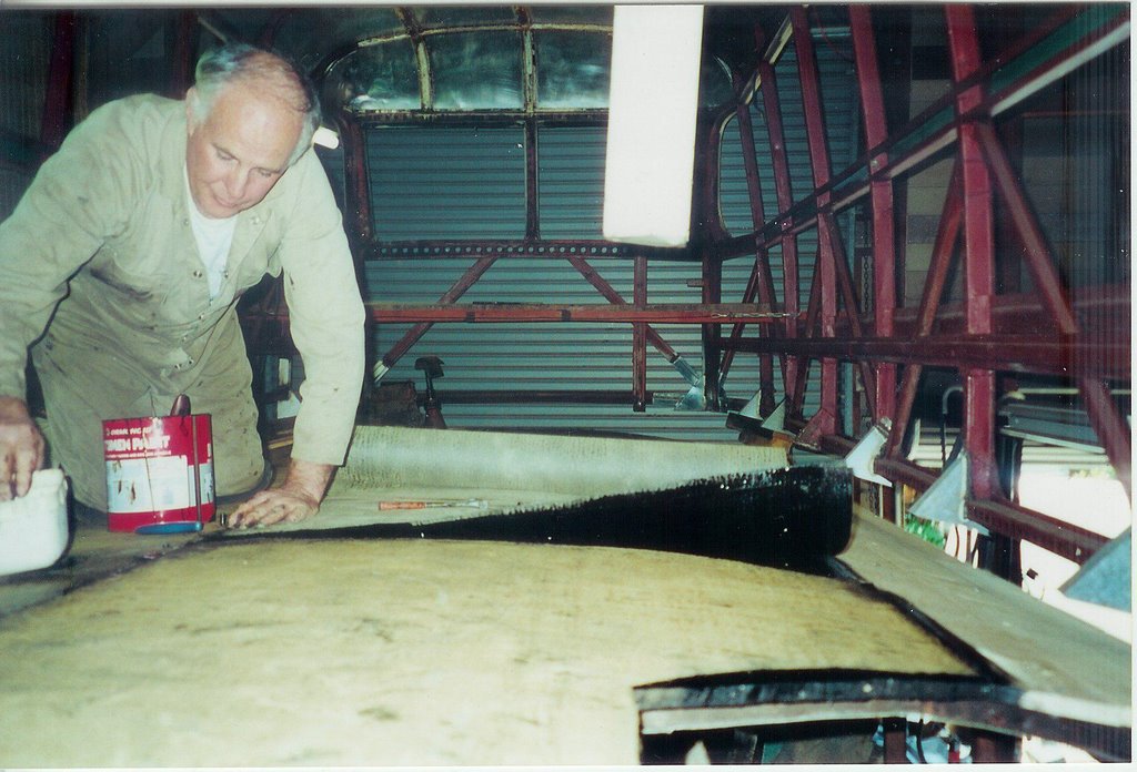
BITUMEN PAINT IS USED TO CEMENT THE MALTHOID DOWN. THE NEW SILL RAILS LOOK AS IF THEY HAVE BEEN THERE FOREVER
With the malthoid down the top deck was ready to be firmly reunited with the bottom deck for possibly the first time in thirty years. Each pillar footing now has four bolts holding it down, through the floor boards to the bottom deck framing, plus another four bolts at each of the corner mountings at front and rear. I remain amazed that it didn’t blow off during the tow from Tempe to Turramurra.

FIRST HESITANT STEPS IN LOWERING THE TOP DECK ONTO ITS NEW FLOOR. THE TWIN ROWS OF BOLTS FOR THE SEAT MOUNTINGS ARE VISIBLE IN THE FLOORING.
It was now December 2000, the end of the millennium. The new millennium (the real one) would begin in 2001, with a list of goals for the year. This included getting the top deck bolted down (completed in the first week of January) , completing the lower deck frame repairs, and the MUDGUARDS. Also at this time I committed myself mentally to restoring the bus to 1937 condition, with high headlights, full swaging of body panels, and wide destination boxes. Up until now I hadn’t really thought about this, except to imagine that red and cream would look nice.
No comments:
Post a Comment